Looking for ideas on how to implement an automation.
-
Hello,
Looking to all the dev's and tinkerers on this community for ideas on how to implement a solution to my problem. Kind of a long intro, sorry.Problem statement:
I have a geothermal heat pump that has a loop that is slightly undersized. During the cold weather months in the Pacific Northwest (one or two months of the year), the loop can get below 32 degrees. If it goes on for a few days, it can generate significant frost heaving in my yard and under the flagstone deck, Actually fixing the issue is cost prohibitive.Current mitigation:
I have DS18B20 tied into Home Assistant and monitoring the temp of the fluid coming out of the loop and if it drops below 35 degrees, MSR triggers a Fibaro Implant to add a resister into the external temp circuit and fool the Venstar to think the outside temp is below 32 degrees and issue a Heat Pump lockout and switch to AUX heat. While this is working fine and the AUX heat is only coming on once or twice a day, I would like to simplify the setup so it runs on something other than HA and MSR. I think they are overkill for my issue. Also want this to be independent of anything else in the house so it can stay behind if I am not around to maintain.I only have two inputs and one output:
Inputs: Loop temp, Furnace running
Outputs: Switch relay to drop resistance to external thermostat connection on thermostat.
Logic is super simple:
If temp is below 36 degrees and furnace is running, turn on relay
If furnace stops, turn off relay.
I am sure even I can figure that out on Python.Trying to determine the best platform for a set it and forget it black box that works with as close to zero maintenance as possible.
Options I have thought of are:
- Pi zero with a GPIO controlled relay
- ESPHome (Not very knowledgeable about that platform, but willing to explore)
- Arduino
- Anything anyone else suggests
Any ideas are appreciated.
@rogero Having owned and operated a commercial data center, when things needed to be uber-reliable, we ditched the PLCs and went straight to relay logic. There's no school like the old school.
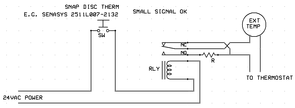
Since your heat pump is likely already making 24VAC for its controls and the thermostat, I'd go with that as a design voltage. A thermostatic switch can close and power a relay that closes the resistor into the external temp circuit. Something like this:
I've shown a Sensasys 2511L007-2132 here, which is normally open and closes below 35F, to control the relay coil. The relay is a simple SPDT type (C form), easy to find in 24VAC.
Assuming I've understood your use of the resistor correctly, in the circuit as shown, one leg of the temperaure sensor is wired to the common contact of the relay. When the relay is de-energized (temp switch open), the temperature sensor is passed through (NC contact). When the temp switch closes and the relay is energized, the resistor is put in series with the temperature sensor (resistance increases) via the NO contact.
Since it helps to know what things are doing without dragging out your meter, I recommend getting a relay with a built-in LED or mechanical indicator so you can see when it's energized (or not). Some also have test buttons to close the relay mechanically. Such a beast is this (there's also a socket for it to make wiring easy, highly recommended).
Sometimes the best smarts are the dumbest.
-
-
Hello,
Looking to all the dev's and tinkerers on this community for ideas on how to implement a solution to my problem. Kind of a long intro, sorry.Problem statement:
I have a geothermal heat pump that has a loop that is slightly undersized. During the cold weather months in the Pacific Northwest (one or two months of the year), the loop can get below 32 degrees. If it goes on for a few days, it can generate significant frost heaving in my yard and under the flagstone deck, Actually fixing the issue is cost prohibitive.Current mitigation:
I have DS18B20 tied into Home Assistant and monitoring the temp of the fluid coming out of the loop and if it drops below 35 degrees, MSR triggers a Fibaro Implant to add a resister into the external temp circuit and fool the Venstar to think the outside temp is below 32 degrees and issue a Heat Pump lockout and switch to AUX heat. While this is working fine and the AUX heat is only coming on once or twice a day, I would like to simplify the setup so it runs on something other than HA and MSR. I think they are overkill for my issue. Also want this to be independent of anything else in the house so it can stay behind if I am not around to maintain.I only have two inputs and one output:
Inputs: Loop temp, Furnace running
Outputs: Switch relay to drop resistance to external thermostat connection on thermostat.
Logic is super simple:
If temp is below 36 degrees and furnace is running, turn on relay
If furnace stops, turn off relay.
I am sure even I can figure that out on Python.Trying to determine the best platform for a set it and forget it black box that works with as close to zero maintenance as possible.
Options I have thought of are:
- Pi zero with a GPIO controlled relay
- ESPHome (Not very knowledgeable about that platform, but willing to explore)
- Arduino
- Anything anyone else suggests
Any ideas are appreciated.
@rogero Had another though about this... since the thermostat is signaling the heat pump to use compressor or aux heat, manipulating those signal wires directly, rather than "fooling" the thermostat wire a resistor on the temperature sensor, is likely a better option.
I wrote the Venstar ColorTouch driver for Vera and Hubitat, so it's the model I'm most familiar with, so I'll base the rest of this on that model (can be modified as needed for other models if they work differently). The ColorTouch's will use W1/O/B to signal heating or cooling, Y to run the compressor, W2 to call for aux heat, and G to run the fan. As usual, R and C are 24VAC supply and return.
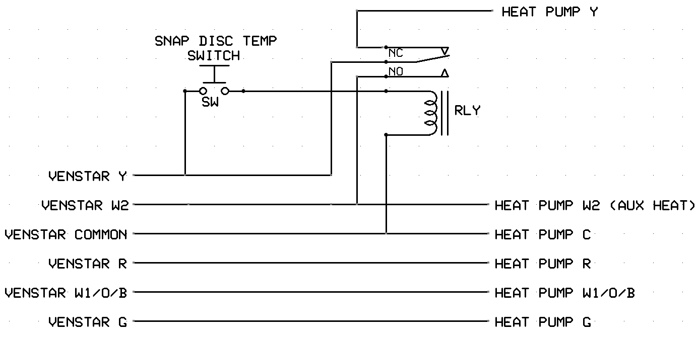
All we need to do is activate the W2 (aux heat) wire instead of the Y (compressor) wire when the temperature is below 35F. That can be done like this:
In this version of the circuit, if the temperature is above 35F, then if the Venstar calls for heat by its Y connection, the relay is inactive so the Y (compressor call) passes through to the heat pump. If the temp is below 35F, when the Venstar calls for heat, the relay is activated, and the Y signal from the thermostat is rerouted by the relay contacts to the W2 (call aux heat) wire to the heat pump, so even though the Venstar is calling for compressor heat, the heating unit will see a call for aux heat.
This is much simpler wiring, too. The relay can be mounted inside the heat pump enclosure next to the control board, and all of thermostat wires come in there anyway so they are easy to intercept and connections will be short and sweet. The snap disc switch can be mounted anywhere (i.e. epoxied to the loop output plumbing) on the end of a long wire pair (I didn't draw in a fuse on that circuit, but probably a good idea). Other than the override from compressor to aux, it does not interfere with the operation of the thermostat.
-
Thanks Patrick and theraldb for your input. The issue I have is that the fluid in the loop stops circulating as soon as the furnace switches to AUX heat. In Patrick's system (either version) the furnace will switch back and forth between HP and AUX several times in one heating cycle. I know because I originally had a thermistor attached to the loop pipe inside the cabinet and connected to the external thermostat connections on the thermostat. So I do need a rudimentary logic engine of some sort.
The MSR logic is this:
If temp is below 36 degrees and furnace is running, turn on relay
If furnace stops, turn off relay.Once the relay trips is has to stay tripped until the heating cycle is finished. I am sure that could be accomplished with relays but I really don't want to muck around inside my heat pump. I already made a stupid mistake with the Venstar 7900 that fried the external temp measuring circuit and had to replace it. (if anyone needs a nice T7900 that doesn't have the external temp circuit but otherwise works fine, let me know)
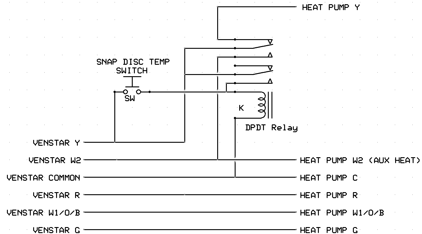
@rogero Here's a version that latches on once tripped and resets itself when the thermostat stops calling for heat.
In any case, this was a fun distraction. And really, this is minimal mucking. I know it looks daunting, but probably the worst you can do if you screw it up is (a) it doesn't work right, or (b) you blow the cheap 3A fuse on the 24V circuit in the unit (just replace it). If you've blown a thermostat with the resistor version, you've already done worse and more expensive than you are likely to do with this.
You can do this simple logic in an ESP32 or ESP8266 quite easily. The problem you always have with such things is getting them powered. You usually end up with a wall wart that's prone to failure. And since the micros are 3.3V volt with low current handling on the I/O pins, you need an interface to drive a relay (more parts or a board that carries both the I/O interface and relay), and you need some kind of enclosure to mount the pieces in, connectors to bring the wires to, etc. IMO, it quickly becomes more complicated than the relay alone. But for sure, you have to what's comfortable for you.
-
I like that design. Actually don't even need to muck around inside the HP. Can intercept the thermostat wires where the come into the furnace closet. need to measure the pipe diameter in the HP and see about getting one of these. http://senasys.com/product/2570l211
Thanks,
Roger -
They sell that temperature switch on Amazon.
-
Depends on what you mean by simple. Since he's measuring the temperature of a water loop, it would require a temperature sensor external to the thermostat on (attached to) that plumbing, so right there, you've reduced the number of available thermostats for the job to those that support external sensors, and that remaining set is likely a bit costly. And you still have to get 24VAC power to that thermostat. Still wiring, really all the same wiring, in fact. An expensive sensor and relay with a front panel, is all a thermostat is, so on net, I think you're paying a lot for a UI you don't need.
-
There are plenty of 24v thermostats with remote sensors here in UK (about £30). The OP wanted "Trying to determine the best platform for a set it and forget it black box that works with as close to zero maintenance as possible."!
So my thinking is thermostat in tandem with external sensor, A little wiring job done. You could also probably use a shelly 1 with temp sensor addon if you want feedback.
-
Appreciate all the discussion. I like Patrick's third diagram, however, looking at discs available I haven't found any with a 5/8 inch diameter connection. Additionally, they are not super accurate according to reviews on Amazon. I might use an ESP32 board with a DS18B20 probe and a DPDT relay in place of the snap switch unless I find one available in my search.
-
R RogerO has marked this topic as solved on
-
So, I have looked into the snap disk thermostats that are shaped to connect to a pipe and found, for the one that meets my specs, that the minimum order is 100 units. Additionally, comments in the interweb indicates that they are not all that accurate. Have been thinking about my design and have come up with this.
I plan to connect a 24VAC to 5VDC step down buck converter to the Venstar common and Venstar Y wires as shown in Patrick's second drawing. Using that to power an ESP32 board connected to a DS18B20 sensor and a relay controlled by GPIO on ESP32.
Logic on this design is pretty simple: Monitor loop temp and switch via relay to aux heat source when temp falls to trigger temp.
Remain in AUX mode until thermostat shuts off and powers off ESP32.
Next time furnace starts, relay defaults to Heat Pump mode until temp drops to threshold again.Questions for those of you with HVAC and ESP32's:
- Will the 24V AC powering the thermostat supply enough power to run the ESP32?
- Are the ESP32's able to withstand multiple power cycles without getting corrupted?
Input's to my design are welcome.
-
The typical fuse on 24VAC control circuits in residential HVAC systems in North America (lot of qualifiers there, sheesh) is 3A, so you're good. I don't think the power cycling will be a problem for the ESP, but YMMV on your buck converter.

